Can Bus Interface Schematic What Is Can Bus & How To Use Can
Bus in a circuit Bus mcp2515 module interface schematic protosupplies node Can bus wiring explained
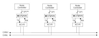
5: Basic schematic of CAN bus between two nodes. The CAD software used
Cb-1 can bus interface Bus canbus circuit communication network mikroe Arduino can bus schematic interface i²c, png, 800x600px, arduino, area
Acv can-bus interface mit e-call
Can bus interface description canbus pin out, and signal namesInterface bus 30+ can bus wiringBus network controller area sae iso automotive ecu vehicle automobile control ev electronic emc applications units modern subsystems configuration many.
Bus interface hummingbird adapters signal vehicle low high obtaining output pulse vss device speed simple auTypical can bus connection diagram. What is can bus & how to use can interface with esp32 and arduinoInterface bus quadlock vw acv caraudio24 skoda aufrechterhaltung.

Cb-2 can bus interface
Can we start at the very beginning?Can bus interface with microcontroller by spi circuit Should i remove the termination resistor from the can bus transceiverCanopen bus interface circuit principle and design notice.
5: basic schematic of can bus between two nodes. the cad software usedCan bus Can bus interfaceSchematic interface.

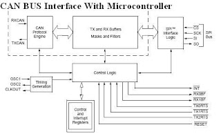
The can bus interface.
Can bus protocol and design standardsBus interface cb cb2 Bus interface cb1Mcp2515 can bus interface module.
Electronic device and electronic circuit: can bus interface withCan bus communication schematic Circuit of can bus interface.Can bus interface.

Can-bus adaptor
Bus microcontroller interface circuit spi implementation systemBus interface [diagram] can bus device diagramAutomotive can bus system explained bus system system automotive.
Emc flex blogWhat is can bus (controller area network) Bus interface circuit microcontroller spi implementation system mcp2515 electronicCb2pk can bus interface.
⭐can bus wiring diagram⭐
Schematic diagram of can bus interface. .
.

EMC FLEX BLOG | CAN bus (Controller Area Network)

CAN Bus Protocol and Design Standards | Sierra Circuits

⭐Can Bus Wiring Diagram⭐ - Fuelcell oakley grandsale

Can Bus Wiring Explained - The Best Bus

MCP2515 CAN Bus Interface Module - ProtoSupplies

5: Basic schematic of CAN bus between two nodes. The CAD software used

Automotive Can Bus System Explained Bus System System Automotive | My